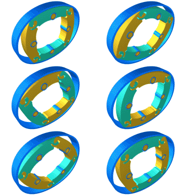
"FORMULA QT" - Quasiturbine Racing Car
(For circuits with Indy, CART series and Formula 1
- F1)
Can a "FORMULA QT" race against the F1 ?
Only the construction of a FORMULA QT will permit to answer this question.
This is a proposal to develop and built a prototype of a
racing car using the new Quasiturbine rotary engine.
Because the Quasiturbine has a much higher specific power density that the
piston engine,
a single Quasiturbine rotor of about 50 cm (20 in.) in diameter by 20 cm (8 in.)
thickness
could develop 1000 HP at only 3000 RPM (twice that if it can reach 6000
RPM?).
Absence of flywheel would allows much higher acceleration.
Since the Quasiturbine has an hollow empty center, a much higher low RPM torque,
and idle at only 200 (two hundred) RPM,
it is proposed to have the racing car rear wheel axle to cross within the
Quasiturbine core,
and to use only a differential clutch coupling (no gearbox at all!). This would much improve
the racing cars endurance.
At this time, the promoter is looking for sponsors to develop
the engineering and validate such a prototype approach.
Next, the No.1 prototype "Formula QT" racing car will have to be built.
Upon satisfactory (or impressive) result, the promoter would attempt to list the
prototype
for "friendly rides" on all major racing circuits, including CART series and Formula F1.
This should provide great visibility to sponsor names and products, and would
prove its open mind to research and new ideas!
The promoter has already interested a major international European
engineering firm currently involved with F1 projects,
which could provide most of the required expertise.
A - The problematic of performing engine ... toward the photo-detonation
The 4 strokes piston of our cars fires once every 2 revolutions and produces a positive torque about 17% of the time, dragging 83% of the time. To obtain a reasonable specific power density, we must use the combustion chamber the most often possible in every minute, which means rotating at undesirable high regime, where it is difficult to avoid the limitations due to gas flow and valves inertia. The high RPM also imposes constraints which require a reduced piston course, which call for a reduction of the crankshaft diameter and a reduction of the engine torque, and consequently a more severe need for the gearbox and on the kinetic aspects like the flywheel, which severely reduces the engine accelerations.Furthermore, the engine combustion chamber is a non-desirable parasite volume from the stand point of energy efficiency, since it must be pressurized in pure lost before being able to produce strong forces on the piston and so to make useful mechanical work. Ideally, the combustion chamber should be the smallest possible, which would imply a high compression ratio. However, the piston meet at least 3 major obstacles which limit the compression ratio : the mechanical robustness, the self-firing (photo-detonation), and the production of polluants. At low compression ratio with a pre-mixed intake, the sparkplug produces a lighting thermal wave which propagates into the chamber, driving a progressive and uniform combustion, but somewhat incomplete. In a similar situation but with a high compression ratio, it is the radiation (light, somewhat like the one of a laser) which light spontaneously, completely and uniformly the combustion (detonation or knocking that piston can not stand, because of the too long pressure pulse that it produces). Already to reach the Diesel mode, a substantial concession has been done, which was the abandon of the uniform combustion from a carburetor for the much less desirable combustion of the localized jet of a fuel injector. Except for the additives which absorb the radiations and increase the octane index, the recent researches aim at optimizing the piston engine deal with variable length connecting rods allowing to continuously set the compression ratio just under the photo-detonation threshold, regardless of the engine regime, but without ever exceeding it. Notice that the photo-detonation occurs at slightly higher compression ratio than the thermal ignition designated in the US as "Homogeneous Charge Compression Ignition" HCCI combustion, in Europe as "Controlled Auto Ignition" CAI combustion, and in Japan as "Active Thermo Atmosphere" ATA combustion. Even if the subject passionate the researchers, the thermal and photonic ignition control in the piston is still an unsolved problem, and possibly a dead-end that the Quasiturbine does overcome!
At low load factor, the intake depressurization of the Otto cycle dissipates power from the engine since the throttle valve is almost closed and the descending piston acts as a clogged vacuum pump against the atmospheric pressure, which vacuum is subsequently partially destroyed by fuel vaporization during the compression. Due to this effect, the engine in Otto cycle opposes to all RPM revolution increase (well known as the engine compression braking) and this intrinsic resistance to speed augmentation is compensated by a constant and important fuel consumption. The photo-detonation mode does not use any throttle valve and accept without constraint all available air at atmospheric pressure (similarly as the Diesel, where the pressurization energy is restituted at the time of relaxation). For this reason, the efficiency at low load factor of the photo-detonation engine is twice that of the conventional Otto cycle, and considering that the load factor of a car is in average of about 10 to 15%, this is not a small difference (saving is still superior in the embouteillages...).
Fortunately, the Quasiturbine allows to solve those dilemma by two unique
characteristics (... and they are not the only ones), which are:
First, to fire
8 times by two revolutions in four stroke mode, which allows to use the combustion chambers much
more often without having to increase the engine RPM, and without facing the
fast gas flow problem, nor the valves inertia since there is none.
Secondly, to
produce shorter pressure impulses with linear ramps permitting to control the
thermal and photonic ignition and to overcome
the obstacles limiting the high engine compression ratio, so increasing the efficiency,
while maintaining the uniform combustion capability and simultaneously reducing the
polluants.
Since
the combustion is initiated by the radiation, the shape of the combustion
chamber and its surface / volume ratio has little effect here, contrary to the
case of the piston. Because it was conceived for thermal and photonic ignition, the Quasiturbine can
not be considered as a "rotary piston engine", nor be correctly
characterized by the piston paradigms.
Here is a list of the main conceptual
deficiencies which limit the
piston engine :
- The 4 engine strokes should not be of equal duration.
- The piston makes positive torque only 17% of the time and drag 83% of the time.
- At mi-stroke, the gas would push more efficiently on a moderated speed
piston,
while it is in fact at its maximum speed escaping in front of the gas.
- The gas flow is not unidirectional, but changes direction with the piston
direction.
- While the piston descent, the ignition thermal wave front has hard time
trying to catch the gas moving it that same direction.
- The valves opens only 20% of the time, interrupting the flows at intake
and at exhaust 80% of the time.
- The duration of the piston rest time at top and bottom are without necessity
too long.
- Long top dead center confinement time increase the heat transfer to the engine
block reducing engine efficiency.
- The non-ability of the piston to produce mechanical energy immediately after
the top dead center.
- The proximity of the intake valve and the exhaust valve prevent a good mixture
filling of the chamber.
and the open overlap lets go some un-burnt mixture into the exhaust.
- The non-ability of the piston to efficiently intake mixture right after the
top dead center.
- The piston does not stand fuel pre-vaporization, but required fuel
pulverization detrimental to combustion quality and environment.
- The instantaneous torque impulse is progressive, and would gain to have a plateau.
- The component use factor is low, and those component would gain to be multifunctional.
- The average torque is only 15% of the peak torque, which imposes a
construction robustness for the peak 7 times the average.
- The flywheel is a serious handicap to accelerations and to the total engine
weight.
- The connecting rod gives an oblique push component to the piston, which then
required a lubrication of the piston wall.
- The lubricant is also heat coolant, which require a cumbersome pan, and imposes
low engine angle orientations.
- The need of complex set of valves, of came shaft and of interactive synchronization
devices.
- The valves inertia being a serious limitation to the engine revolution.
- The internal engine accessories (like the came shaft) use a substantial power.
- The poor homokinetic geometry imposes violent accelerations et stops to the piston.
- Quite important noise level and vibration.
- At low load factor, the intake depressurization of the Otto cycle dissipates
power from the engine (vacuum pump against the atmospheric pressure).
B - The Quasiturbine engine
http://quasiturbine.promci.qc.ca
In short: The asymmetry of the strokes
and the precocity of the mixture intake and gas expansion
(without excess volume during expansion) allow for a better initial mechanical energy
conversion.
During 2 rotations, the 4 strokes piston completes 4
strokes while the Quasiturbine completes 32 !
Continuous intake and exit flow make better use of intake
and exhaust manifold,
and allow to reduce the weight and the volume of the engine by a factor 4.
A faster reduction in the combustion chamber of the temperature,
the pressure and the confinement time leads to less NOx production,
and less heat transfer toward the engine block, all contributing to improve the
efficiency over the piston engine.
For over 50 years, researchers have been dreaming about the perfect engine,
having uniform combustion, with a small combustion chamber (high compression
ratio).
This is what the Quasiturbine does by producing a much shorter pressure pulses
(particularly QT-AC with carriages),
and furthermore accepting photo-detonation, because compression and relaxation
slopes are very nearby in time.
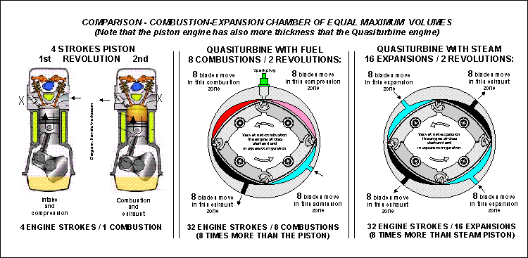
Click here for a 2000 pixels high resolution
image
These diagram explains the sequence of operation of internal combustion
and pressurized fluids (air or steam) Quasiturbine. Notice the 32 strokes per 2
revolutions!
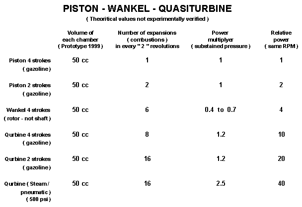
Table comparing the power output of different engines in different operation modes.
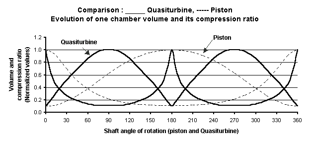
Quasiturbine model of series AC (with carriages)
This graph compares the volume variation within the piston
and the Quasiturbine.
notice the Quasiturbine linear pressure ramp with discontinuity at TDC.
.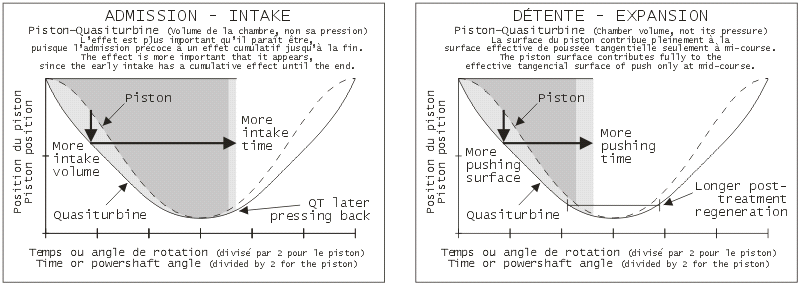
Quasiturbine model of series AC (with carriages)
This graph shows the improved intake characteristics of the
Quasiturbine compare to the piston engine.
The Quasiturbine acts naturally aspirated almost like a piston engine having a
turbo!
But why does the Quasiturbine
stand what the piston can not tolerate?
Because kinetics in the vicinity of the TDC of the
"piston" and the "QT-blade" are diametrically opposed, both in
volume and speed. In volume, because the piston passes at the TDC at almost constant volume, whereas
QT-blade (specially Model QT-AC) passes the TDC with a discontinuous varying
volume (volume vary quickly linear downward and ascending, where the tip is an abrupt turn
around). In speed, because the piston
passes at the TDC with one discontinuous speed (deceleration, stop, and
acceleration in opposite piston), whereas the QT-blade passes the high point at constant speed (with moreover
a null radial
component). Two mechanical considerations rise directly from these
physical characteristics. Firstly, the piston is in rise (kinetic ascending)
when early photo-detonation comes to strike it (kinetic downward), and
like two objects moving in opposite direction run up very violently, it
piston resists badly, whereas the QT-blade passes the TDC at constant kinetic
and null radial speed. Second, the short tip impulse of the Quasiturbine retains the pressure less longer than the long
sinusoidal impulse of the piston, and consequently the QT-blade tires much less.
Centrifugal force on the blades of Quasiturbine also helps to contain high
pressure.
Notice that because of its crankshaft, the Wankel behaves like piston
near TDC.
For
all those reasons, and considering what it is intended to achieve,
the Quasiturbine can not be considered as a "rotary piston engine".
Piston paradigmes do not apply to the Quasiturbine!
Readers unfamiliar with rotary engines are invited to
read also the section :
Why is the Quasiturbine so exceptionnal ?
http://quasiturbine.promci.qc.ca/QTperformance.html
Why is the Quasiturbine superior to the
piston engines ?
http://quasiturbine.promci.qc.ca/QTPiston.html
and
Why is the Quasiturbine not a Wankel's type engine ?
http://quasiturbine.promci.qc.ca/QTpasWankel.html
C - Racing car Quasiturbine engine integration concept
Because the Quasiturbine has a much higher specific power
density that the piston engine,
a single Quasiturbine rotor of about 50 cm (20 in.) in diameter by 20 cm (8 in.)
thickness
could develop 1000 HP at only 3000 RPM (twice that if it can reach 6000
RPM?).
Absence of flywheel would allows much higher acceleration.
Since the Quasiturbine has an hollow empty center, a much higher low RPM torque,
and idle at only 200 (two hundred) RPM,
it is proposed to have the racing car rear wheel axle to cross within the
Quasiturbine core,
and to use only a differential clutch coupling (no gearbox at all!). This would much improve
the racing cars endurance.
The promoter has already interested a major international
engineering firm currently involved with F1 projects,
which could provide most of the required expertise.
D - "Formula QT" Prototype construction
At this time, the promoter is looking for sponsors to develop
the engineering and validate such a prototype approach.
Next, the No.1 prototype "Formula QT" racing car will have to be built.
E - A great sponsor opportunity on CART and Formula F1 circuits
In 2 or 3 years, upon satisfactory (or impressive) result, the promoter would
attempt to list the prototype
for "friendly rides" on all major racing circuits, including CART series and Formula F1.
This should provide great visibility to sponsor names and products, and would
prove its open mind to research and new ideas!
F - What would accelerate this project?
International sponsors looking for top visibility in 2
to 3 years
(Not necessarily engine manufacturers:
Petroleum companies, car accessories products, tires products, mining, metal,
airlines, energy, computers...)
A list of well known racing-car pilots supporting the project by booking test-drive of this future generation racing car.
A FORMULA 1 or CART Series recent technology unused car frame donation?
Qualified racing car designers support and advice.
International engineering firms contribution to the
engine prototype and racing car integration.
(A large French firm has already given is support to this project)
Racing car machine-shops to assist in making QT engine parts and integration fixtures.
A shop and mechanics affiliated to a high class racing circuit where the project could be assembled.
International communication firms proposing the projects to divers possible customers and sponsors.
An international racing manager to promote and book this FORMULA QT prototype in future events.
With curious people like you referring the project to your contacts...
| Return to main menu |
Quasiturbine Agence Inc., Promotional
Agent for the Quasiturbine Continuous Combustion Rotary Engine or Compressor
Casier 2804, 3535 Ave Papineau, Montréal Québec H2K 4J9 CANADA (514) 527-8484 Fax (514)
527-9530
http://quasiturbine.promci.qc.ca
quasiturbine@promci.qc.ca
