(In stock)
Quasiturbine QT.6LSC
Pneumatic - 1,5 kW
(A 600 cc litres displacement per revolution)
COMPLETE and RUNNING!
3900 US$ (see purchase order form below)
Air freight available worldwide.
(Custom exempted within North America NAFTA zone??).
(Check for « on the shelf » inventory...)
This chainsaw is shown only as a sample of 1.5
kW QT engine application.
The chainsaw is not available for sale at
this time.
Quasiturbine Has No Vane
Unlike vane pumps, which vane extension is important and against which
the pressure acts to generate the rotation, the Quasiturbine contour seals have an
imperceptible extension and the rotation does not result from pressure against these seals.
Since the cylindrical (or oval) stator of vane devices has a radius of curvature
greater than the rotor, the two surfaces (rotor - stator) cannot reach a close
fit at top dead center (TDC), while the surfaces of both the rotor and stator of
the Quasiturbine fit exactly against one another to produce a high compression
ratio. This is why QT is efficient (less pressure charging losses), and this is why there is no vane combustion engine.
Quasiturbine publishes « efficiency data ».
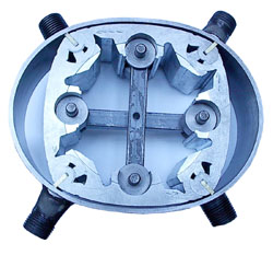
QT.6LSC (shown here) without the differential and the central shaft.
Quasiturbine Model QT.6LSC has a volume of 75 cc per chamber,
and swept 8 chambers per revolution (4 on the top, 4 on the bottom),
which totalized 600 cc per revolution.
Quasiturbine Uniflow Characteristic
In most reciprocating piston engines, the flow reverses
its direction at each stroke (counter-flow). By entering and
exhausting the cylinder by the same port, the cylinder valve and walls are
cooled by the passing exhaust, while the hotter incoming admission
is wasting some of its energy in restoring the temperature. Some energy is
further lost in reversing the motion momentum of the mass of gas within
the piston. The aim of the piston uni(directional)flow
is to remedy this defect by providing an exhaust
port at the end of the stroke, making the gas flowing only in one
direction, but has the inconvenience of recompressing some residual
cylinder gas. Quasiturbine is a uniflow engine, with the further
advantage of not recompressing any residual gas, resulting in superior
energy efficiency. Recompressing residual gas means some reversibility
losses, and the pressure increases makes a substantial restriction to the
initial flow into the chamber, not to ignore the truncated cycle
near bottom dead center - None of this with the Quasiturbine.
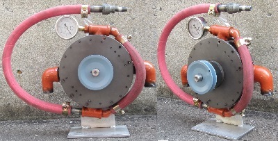
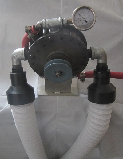
QT.6LSC Pneumatic (gas) 1.5 kW
QT.6LSC Product Description
The Quasiturbine pneumatic unit is very
similar to the steam one, except for thermal dilatation provision,
lubrication and corrosion consideration.
Each chamber has a 75 cc maximum volume, and the motor expands 8 chambers per revolution:
Displacement: Total = 8 x 75 cc = 600 cc intake per
revolution.
Intake Volumetric Flow Rate = Engine displacement x RPM
Cylindrical outside about 8" (~20.3 cm) in diameter excluding peripherals.
Thickness 2,5" (~6,4 cm) excluding shaft and peripherals.
The casing and rotor are made of metal (no aluminum at this time).
Power shaft: 3/4-inch (~1,9 cm) diameter throughout.
2 intake ports 1/2"
male NPT pipe threads.
2 exhaust ports 1"
male NPT pipe threads.
Weight (all metal) about 20 pounds (9 Kg).
Simple in-line lubrication.
Not optimized as compressor.
Present typical limitations under proper lubrication:
- Intake pressure: 60 psi (4 bar) peak.
- Revolution: 600 rpm.
- Block temperature: Under 60 C (150 °C (300 °F) upon
special request.
- Torque (2009 version and later):
Up to
30 N-m (25 pound-foot) peak (with no step down gearbox).
- Power 1,5 kW (2 HP) peak
- Pressure-flow energy conversion: +/- 80 % of theoretical single-stage
(optimum across the range - no off-peak penalty)
Maximum Temperature Control:
Provision for thermal expansion is for now limited
to a air motor rotor temperature of 60 C, and 150 C (300 F)
upon special request. Exceeding limit temperature is
noticeable by a sudden rpm reduction, in which case
one should not insist and let the QT cooled down
before trying again in proper condition.
Hydraulic : This Quasiturbine must not be use
with incompressible fluid (liquid hydraulic mode) - When possible, avoid
excessive internal liquid condensation and do not flowed with lubricant.
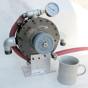
Quasiturbine Model QT.6LSC Steam (Pneumatic)
Usable with intake pressure from 1 to 60 psi (4 bar) peak!
Not being
mass produced, Quasiturbines are like precious « Ferrari »,
while the «
energy cost » to run less efficient equipments may lead to no overall saving.
Among the new emerging technologies like
hybrids, hydrogen, fuel cell, PV solar, in-wheel motor, power windmill, nuclear thermal...
the Quasiturbine is by far the least expensive innovation to familiarize with!
QT.6LSC Typical Characteristics
QT.6LSC theoretical main characteristics can be approximated from 3 parameters:
-
Instantaneous maximum torque for 2 opposed working chambers is 8.0 + 8.0 = 16
N-m / bar (0.4 + 0.4 = 0.8 pound-foot / psi). The average torque is 65 % of the
instantaneous maximum, which is 10.4 N-m / bar (0,5
pound-foot / psi) differential effective
pressure through the motor, assuming no truncated intake);
-
The RPM revolution within reasonable range and the intake geometric flow
(75 cc
x 8 chambers per revolution x rpm, assuming no truncated intake);
-
The power output which is proportional to the product: Torque X rpm.
Typical value given as indication only. May vary from one QT to another.
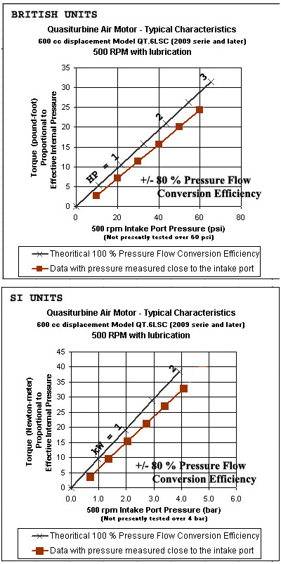
This graph is from a QT.6LSC Air Motor
at 500 rpm and up to 60 psi (4 bar), and is given as an indication.
Perfect « single-stage theoretical expander curve » is shown for
comparison.
Ratio of the 2 curves is +/- 80%
(optimum across the range - no off-peak penalty)
Air (gas) consumption: For most positive
displacement engine, the Intake
Volumetric Flow Rate is the displacement
time the rpm, which gives for the QT.6LSC:
=
600 cc x 500 rpm = 0,3 cubic meter per minute.
The « minimum theoretical air consumption » is exceeded by the same ratio as
pressure-flow efficiency, which correspond to substantial saving when
compared for example, to low torque high rpm vanes motors (see details below).
Theoretical Output Power Extrapolation: Pressure increases
both the rpm and the torque. Since the power is proportional to the product of rpm
X torque, the power output is roughly proportional to the square of
the pressure. Increasing the pressure by 3 fold would then increase
the power by 9 times! (2 kW at 4 bar would theoretically become 18
kW at 12 bar - or - 3 HP at 60 psi would theoretically become 28 HP at
200 psi). This is of course outside the operational range of the present
machines...
Expander Efficiency
Expanders expand the gas of a reservoir, but not necessarily the gas within the expander.
The efficiency is a ratio expressed in %. It is used to evaluate an
equipment result in relation to either the incoming energy (Semi absolute
efficiency - when for example for gasoline engine: energy extraction,
transportation and refining are discarded), either in relation to a partial form of
energy (relative efficiency), or in relation to the result of an other
equipment or reference theory (comparative efficiency). To further
complicate the situation, different engines with same efficiency on bench
test will lead to different efficiency applications (in mobility for example,
due to weight and gearbox
requirement). No correct efficiency interpretation is possible without
knowing detail calculation. Consequently, it is
not possible to optimized simultaneously an expander for maximum power and
maximum efficiency, a choice must be done.
The efficiency is generally in relation to the task an equipment is
attempting to accomplish, and in the present context all « single-stage
expanders » can conveniently be compared to the « single-stage expander
theoretical model (without intake cut-off) », which is simply a piston
making work under pressure, while moving in an infinitely long cylinder
(which is a useful reference):
Theoretical Single Stage (TSS) Calculation:
British units: (See theoretical line on the British units graph)
Power (HP) = Pressure (psi) X Volumetric Flow Rate (VFRcfm) / 229
(As an example: 1 HP = 7.63 VFRcfm at 30 psi)
Metric units: (See theoretical line on the SI units graph)
Power (kW) = Pressure (bar) X Volumetric Flow Rate (VFRm3/min.) X 1.70
(As an example: 1 kW = 0.29 VFRm3/min at 2 bar)
Devices are not all equally efficient when attempting to match
this theoretical piston-cylinder model, but Quasiturbine does it (with no
intake cut-off) at +/- 80
% of the perfect theoretical single-stage (with potential improvements up
to 95 %). To reach such a level of comparative efficiency, other concepts
need to run at nominal power only, or to use intake cut-off techniques. Such techniques are adaptable to
the Quasiturbine as well, for an overall top performance.
Note: There is more intrinsic energy in the compressible incoming flow
(energy accumulating in the infinitely long cylinder as the piston moves)
that single-stage expanders are not attempting to recover (it is not
within their tasks), and which end up in the exhaust. Additional recovery
would require cut-off intake valve and multi-stages (QT?) expanders, but
at a much reduced machine specific power density (larger expander and
higher cost).
Most current compressors are not design for
20 - 60 psi output, which make them running at only a fraction of their nominal
power when feeding a low pressure Quasiturbine. For this reason, compressor must
generally be oversized to sustain experimentation, or the system must have an
important air reservoir. In the case of very high pressure gas tank, not only one
wants to harvest the energy actually in the pressurized air tank, but also take
advantage of the energy amplification possible from using available external
heat. On one side it
is not efficient to make a too important pressure drop into one expander because
the adiabatic cooling will strongly reduce the pushing pressure, and the exhaust
gas will be thrown out at valuable high pressure. On the other side, using a
pinhole regulator will dissipate pressure energy, but will allows the reduced pressure
gas to be thermalized, such as to run the expander with much less adiabatic
cooling and less gas pressure energy thrown at exhaust. Both methods are
compromises. Multi-stages with heat input is hardware intensive, but the best
way to get the most mechanical energy out of a high pressure gas tank with an
external available heat source...
Selecting a high efficiency engine is a good start, but other system
components and thermodynamic cycles also impact the global system
efficiency, which should not be confused with the engine component efficiency.
Comparing Quasiturbine to Vane Motor
Since the cylindrical (or oval) stator of vane devices has a radius
of curvature greater than the rotor, the two surfaces
(rotor - stator) cannot reach a close fit at top dead
center (TDC), while the surfaces of both the rotor and
stator of the Quasiturbine fit exactly against one
another to produce a high compression ratio. This is
why QT is efficient (less pressure charging losses).
Several manufacturers are offering quality products based on Vane Motor concept.
As a matter of preliminary comparison (assuming intake pressure near the
effective internal pressure), here are some typical data of
Quasiturbine versus a GAST air product (calculated
comparison subject to later experimental confirmation
under same running pressure):
Quasiturbine QT.6LSC under 4 bar (59 psi) and 500 rpm: 1.7 kW // 2.3 HP
Detail:
quasiturbine.promci.qc.ca/EProductQT75SCPneumatic.htm
Intake Volumetric Flow Rate (IVFR) = 0.3 IVFRm3/min // 10.6 IVFRcfm
Effective Displacement: 0.3 IVFRm3/min / 500 rpm = 600 cc // 36.6 po3 per revolution
Consumption: Free air* = 1.5 m3/min of free air // 53 cfm of free air
(* Estimated at 4 bar (59 psi) as 5 times the IVFR of 0.3 m3/min).
Consumption Specific = 0.88 m3/min-kW of free air // 23 cf/min-HP of free air
Theoretical Single Stage Power (TSS) = 4 bar X 0.3 m3/min X 1.70 = 2.04 kW
Theoretical Single Stage Power (TSS) = 59 psi X 10.6 IVFRcfm / 229 = 2.74 HP
QT Performance: 1.7 kW / 2.04 kW = 2.3 HP / 2.74 HP = 83 % of TSS
GAST 4AM Vane motor under 7 bar (103 psi) and 3000 rpm: 1.3 kW // 1.7 HP
Detail:
www.gastmfg.com/pdf/airmotor/specsht/4AM.pdf
Intake Volumetric Flow Rate (IVFR)* = 0.25 IVFRm3/min // 9.2 IVFRcfm
(* Estimated at 7 bar (103 psi) as 8 times less
the flow of 2.0 m3 free air /min).
Effective displacement: 0.25 IVFRm3/min / 3000 rpm = 83 cc // 5.1 po3 per revolution
Consumption: Free air = 2 m3 free air /min // 70 cfm of free air
Consumption Specific = 1.53 m3 free air /min-kW // 41 cf/min-HP of free air
Theoretical Single Stage Power (TSS) = 7 bar X 0.25 X 1.70 = 3.0 kW
Theoretical Single Stage Power (TSS) = 103 psi X 9.2 / 229 = 4.0 HP
GAST Performance: 1.3 kW / 3.0 kW = 1.7 HP / 4.0 HP = 43 % of TSS
From the energy reversibility (heat lost) point of view, the
difference is even greater, as one consumes its air
volume at 7 bar (100 psi), while the QT consumes it at
only 4 bar (60 psi).
In conclusion, the Quasiturbine concept (without intake cut-off)
operates at 80 % of the Theoretical Single Stage
(TSS) Power, compared to 40 % for Vane Motor concept
(even when using some intake cut-off saving), with
QT potential to reaches 95 % under high mechanical
tolerances. Furthermore, QT operates in the most demanding conditions of
high displacement, low pressure and high torque.
Consequently, the Quasiturbine air/steam concept
exceeds substantially the relative efficiency of
Vane Motor concepts, which is consistent with the
vane loading chamber volume lost. For many
applications, there is little or no benefit to use
low cost vane air motor when the pressured fluid
consumption is the dominant cost factor.
QT Lubrication
Periodic oil needs to be injected into the motor
intakes steam flow. The best is oil injection within one of the intake
port using a small pulsed pump (electrical or pneumatic). An other
convenient way is to keep an oil reservoir pressurized (with air?)
slightly over the QT intake pressure, and to simply control the oil flow
through a needle valve.
Pneumatic tools oil is a good choice. Air motor
can also use standard steam
cylinder oil ISO 460 which contains 4% tallow oil.
This is the grade of oil that the “ride-on” locomotive community uses. It
is generally available in 55 gallon drums, but Sulphur Springs Steam Models
sales@sssmodels.com
provides it in quart cans. Chevron USA has a relatively new steam cylinder
oil on the market that is lighter in viscosity than ISO 460 by about half
(1103 SUS vs. 2335 SUS @ 100 F). Other steam oil may do as well, search "
steam cylinder oil" on the web for local suppliers. It does
not require much oil, and it can be recirculate.
Never use motor oil or inappropriate lubricant.
Never use oil with additive like antifriction,
because large air flow or steam oxidized the oil and precipitate the
additives in « glue like product » fatal to the Quasiturbine operation, as it
will oxidize and degrade into solid or viscous material under steam
contact. If this happen, attempt cleaning the engine with a glass of
kerosene in the intake, while turning the engine slowly by hand. Re-oil
properly.
Feed Line Capacity
Flow velocity near a
piston valve is always impressive, and it is not
different with the Quasiturbine intake ports. To
sustain 500 rpm in a 600 cc displacement QT.6LSC,
the intake flow rate must be (600 cc X 500 rpm) =
0.3 m3 / min.. Knowing that a 1/2 inch
diam. tubing contains 0.125 litre / meter long, this
correspond to a flow velocity in the tube of :
(300 litres / min.) / (0.125 litre / m) =
40 m / s or 150 km / h
Could be half, considering
that the Quasiturbine has 2 intakes which could be
feed individually. Velocity near the intake ports
will be even higher. Consequently, such a relatively
small tubing must be quite short (or act as a
limiting safety factor to protect the unit?). Notice
that once the pressurized fluid gets into the
engine, the flow velocity reduces to match the
tangential rotor speed, which is:
(engine
perimeter = 50 cm) X 500 rpm = 4 m / s = 15 km / h
and flow speed increases again into the exhaust,
which must show minimum restriction.
Good example of minimum exhaust flow restriction
after
air expansion (few meters).
This preserves pressure differential and full power of the QT.
An appropriate steam condenser close to the exhaust port
could also be a valid solution.
Across an expander, the mass flow stays constant,
but the volumetric flow does not.
Feed line consideration is particularly important for
steam, as pressure drop along the feed line and
associated condensation generate undesirable
condensate, which should be remove somehow at the
engine intake for smooth operation.
A good set-up require a
short and generous size feed line and exhaust line.
It is also preferable to add an damper-buffer tank in the
vicinity the expander to absorb pressure
fluctuation and provide a smooth engine flow.
Sealing the Quasiturbine
As delivered, the Quasiturbine has no pretention to
be a sealed machine, and in particularly at the shaft bearings
(leak increasing with exhaust back pressure).
Because Quasiturbine can be used with a multitude of
gases (some environmentally sensitive), and
considering the multitude of seals available, it is
up to the owner to apply if
needed, its proper sealing solution to the system
(Look in Search Engine Image for «
Axial Radial Shaft Seal » or «
Replacement Cartridge Mechanical Seal »).
Some seals cost less that 10 $ to buy, but high temperature seal could be a challenge.
General info at
www.skf.com/files/889495.pdf .
While thin wall enclosure is an ultimate solution
for critical situation, stuffing
box (made of a simple outside washer bolted to the
engine block) with Graphite Coating Packing Sealants
could often be an acceptable straight forward
solution.
Using Air Motor as Compressor
Turning in reverse a Quasiturbine air motor will
(in principle) make it act as a compressor (not efficiently if not
properly design for that role). However, the direction of rotation can be
keep the same, if both exhausts are plug by a small check valve line
taking the exhaust pressure exit as the compressor output. Then, to
prevent the air motor intake two lines to be vacuumed, a check valve on
them allowing-in atmospheric air will suffice. This kind of switching
motor-compressor mode without changing the direction of rotation will
later be useful for application
like windmill back up pneumatic air storage or vehicle breaking energy
recovery device.
QT.6LSC Pneumatic - Purchase Order (PO) Form
To : Quasiturbine Tronçonneuses
Casier/Code/Porte 2804 - 3535 Papineau
Montréal Québec H2K4J9
514-527-8484 Fax: 514-527-9530
Associated website :
www.quasiturbine.com
Quasiturbine model QT.6LSC Pneumatic (1,5 kW peak)
with rotating central differential and shaft
is intended for integration research, demonstration and projects.
To be used only under competent supervision.
Guaranty is limited to replacement (pick-up) of defective parts.
Sale done FOB Montréal, Québec Canada
No Canadian local sale taxes on export.
Not including the shipping (pick-up)
and custom fees
(NAFTA Exempted?) H.S. # 8413.81:
3900.00 US$
Money rate conversion at
http://fr.finance.yahoo.com/m3
The web page
quasiturbine.promci.qc.ca/EProductQT75SCPneumatic.htm
is an integral part of the present purchase order
and constitute the terms and conditions accepted by the buyer.
__________________________________
Authorized Officer
Date: ______________
Company Name: __________________________
Shipping address: _________________________
_____________________________________
Phone: ____________________
Fax: _______________________
www.___________________________
email:__________________________
Package: Weight: 14 kg / 30 pounds.
Size: 30 cm X 30 cm X 26 cm high / 12 X 12 X 10 inches height.
Email the form to
info@quasiturbine.com or fax to 514-527-8484.
An invoice will follows with payment instructions.
(Terms: Pick-up or shipping the day the funds transfer is received).
ADDENDUM
Electric Generator
A 12 poles AC generator would be a good RPM
match with Quasiturbine.
For information (not necessarily recommendation),
see also the following:

The PTO Generator considered by APUQ on their website at
promci.qc.ca/pureinvention/apuq/APUQGeneratriceVapeur.htm
A fraction of the engine output is lost in the electric conversion process.
Example: 8 kW for 900 $ at
http://www.northerntool.com/shop/tools/product_200308467_200308467
Also available up to 150 kW in European standard (ex.
Winco)
IDEAS? (Not tested possibilities...)
Rotary Pressure Regulator:
What about an "energy recovery rotary pressure regulator" ? An
interesting application of the steam Quasiturbine is to recover the high pressure energy at
pressure reduction stations. Instead of using a
conventional cooling station,
a steam Quasiturbine will rotate under the
pressure differential and the flow will be controlled by the rpm, i.e. the
torque applied on the Quasiturbine shaft. This way, the Quasiturbine can
transform the pressure differential into useful mechanical work to run pump,
compressor, ventilator, electricity
generator or locally convert the energy in high grade heat. Because
conventional turbines can not be widely modulated in rpm and load, they are not
suitable for gas flow and pressure control, while the Quasiturbine is
essentially a closed valve at zero rpm (subject to appropriate construction), and has high efficiency at all torque
and all flow rpm. All
experimental demonstration has to be done only by steam
experts and under all current rules and regulations.
ORC (Organic Rankine Cycle):
Engine suitable for ORC (Organic Rankine Cycle) in Solar, Geothermal and Waste Heat Recovery.
QT Operation
It is the buyer and/or operator
responsibility to comply with all applicable national
and local laws and rules, including those on security and pressurized products.
In several countries 1 bar (15 psi) is considered as high pressure!
-
It is the buyer and/or operator responsibility
to comply with all applicable national and local laws and rules,
including those on security and pressurized products.
Current research lab precaution and procedure must apply.
-
Familiarize yourself well beforehand with the Quasiturbine
technology (see the associated site at:
www.quasiturbine.com ).
-
Remove the
condensate in the steam line before starting and continuously if necessary, to insure smooth running.
Important: Use only degasified liquid to make vapor or steam. See
http://en.wikipedia.org/wiki/Degasification
-
For optimum performance, the feed line must be well
balanced between the two intake ports, which must be done by ending the line
passed the 2 T by an accumulator (buffer) tank (minimum 20 litres), on which
the pressure gage can be located.
-
Make it turns gradually (without abrupt acceleration).
-
Ensure that the rotor is adequately lubricated (pneumatic tool oil
only). (Never use oil with additive like antifriction,
because large air flow or steam oxidized the oil and precipitate the
additives in glue like product fatal to the Quasiturbine operation). The
best is oil injection within one of the intake port using a small pulsed
pump (electrical or pneumatic). A convenient way is to keep the oil
reservoir pressurized slightly over the QT intake pressure, and to simply
control the oil flow through a needle valve.
-
Ensure that the hoses and fasteners (particularly the flexible
ones) are of quality and well anchored.
-
It is recommended not to exceed 600 RPM and/or 4 bars (60
psi) at the pressure gauge when with load, half without load. 60 C max. No
free running at more than 20 psi.
-
Avoid flow restriction at exit.
-
Intake steam must be reasonably clean, and always
with degassed fluid.
QT Safety Precautions
-
These unit must be operated under the
constant supervision of qualified adults. Heat protection should be use at all time.
-
Anchor the unit well before each start-up.
-
Never exceed the limits and suggested conditions of operation.
-
Wearing safety glasses, mask and fastened hair is recommended.
-
The demonstration room must be well ventilated.
-
Check the tightening of the bolts and adapters. Be aware of the rupture
or the decoupling of any of the flexible hoses.
-
Have a distant valve at hand to cut the air/steam flow as needed.
-
Particularly during breaking-in under compressed air, it can happen that
the rotor stops at a dead point, and refuses to turn when the pressure is
applied. This situation is unstable and call for urgent pressure release. In
absence of pressure, slightly turn the rotor with the central shaft and pressurize it again...
-
During the demonstration, nothing should approach the central zone of the rotor;
make observations at a distance of 50 cm (20 po.) or more.
-
Always remain vigilant and careful!
QT Sale Details
GENERALITIES
-
Sale and operation are restricted to adults only.
-
Pneumatic air-nitrogen only (less than 4 bar - 60 psi),
no steam conversion attempt must be made (could be dangerous).
No liquid hydraulic mode.
-
Additional parts of replacement can be ordered by owners.
CONDITIONS
-
The Purchasers release the
manufacturer from all responsibilities relative with the use.
-
Guaranty of the manufacturer is limited to the replacement
(Pick-up) of the defective parts.
-
The present document and conditions must be transferred to the chain of
future owners of the unit.
-
If there is intellectual propriety risk, the manufacturer can simply
refund and not deliver.
-
The purchasers accept the present page as part of the purchase
order agreement and invoice.
PRICE AND SHIPPING
-
The price does not include the applicable local
sale taxes if required, and not
the shipping (pick-up) and custom fees.
-
The insurances and customs fees are the responsibility of the purchaser.
-
As possible, shipping (pick-up) will be made on schedule following the reception of the
payment, or according to the production capability of the moment (Check for « on the shelf » inventory...).
-
Failure of the buyer to make final payment or take delivery of the unit
within 3 months of the notice of completion will be interpreted as an abandon of the product without compensation.
QUASITURBINE TRONÇONNEUSES
(Manufacturer under a privileged QT-BLADES supply license agreement)
Casier/Code/Porte 2804, 3535 Ave Papineau, Montréal Québec H2K 4J9 CANADA
(514) 527-8484 Fax (514) 527-8484
Associated website www.quasiturbine.com
info@quasiturbine.com
Subject to changes without notice - January 7, 2019
|
