It is good to have a basically efficient motor / expander,
but to get the most of it, it must be used
in an efficient manner.
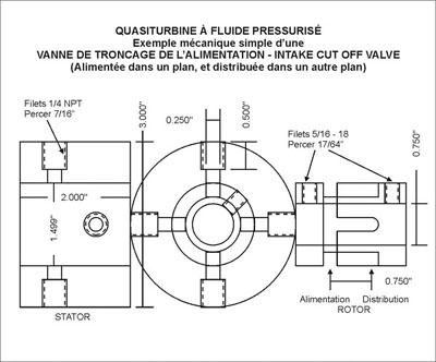
Intake Cut Off Valve
Single Stage Efficiency Versus Power
Note: This is not necessary for the motor to run great!
Quasiturbine Efficiency
The Quasiturbine is quite efficient as is by many standards.
But for those who want still more efficiency, the intake cutoff is
a possibility for the compressible fluid modes (air / gas / steam motor).
For all Single Stage Positive Displacement Expander (including piston)
without cut-off valve, theoretical efficiency (not comparative efficiency
to SSE Model) is 71 % at 1 bar, but fall under 42% at 7 bar, while
maintening the advantage of full nominal motor power output. Vane expander
are not doing as good due to chamber load losses (see theory section
below).
Power Level versus Efficiency
First, great care must always be taken not to confuse
motor efficiency with the system efficiency. A 100% motor
efficiency could still led to a low system efficiency, as efficiency of
each system component multiply themselves... Efficiency is not a constant
motor parameter, but it depends very much of the operation conditions and
regime, and of the intake cut off decision in compressible fluid mode.
Very often, it is not possible or even suitable, to keep a motor running at its optimum
efficiency regime.
When a motor is used with compressible fluid in
pneumatic, steam, expander or turbo-pump, there is always an inerrant
competition between the Power level and the Efficiency. Longer the gas
pressure is provided to the chamber cycle, more power it will produce, but
less expansion this gas will have within the machine, and consequently
less gas relaxation will occur before the exhaust time - An efficiency
penalty imposed when high power level is demanded. Optimum would be a perfect
reversibility situation, where the chamber is initially and rapidly
pressurized (ideally with hot gas) to such a level that expansion ends
near the atmospheric pressure and temperature (or condensation condition) at exhaust time. In such a
system, increase in Power can be obtain either by increasing the intake
pressure, or by increasing the open duration of the intake valve cut-off.
The practice of truncating the intake cycle is common
to all positive displacement engines. Old steam locomotive did have some
cut off capability once cruise speed attained, as have many of the today
vane type motor (fixed expansion ratio). Of course, his valve must
be synchronized somehow with the motor shaft or the chamber cycles, and the in-line gas pressure
regulating reservoir must be located before the cutting valves.
One should also remember that heat is produced when
compressing a gas, and as much as possible, this heat should not be
discarded by cooling the compressor, but rather stored with the compressed
air in an insulated pressure tank (if the compressed gas is going to be
relaxed within hours of its compression). This heat would then be
efficiently used in the adiabatic cooling relaxation process and insure a
much better reversibility of the compression-expansion cycle.
For applications using a fix air reservoir (like high pressure cylinder),
intake cut off power reduction can
generally be compensated by using higher intake pressure, and by doing so,
the overall energy available from a cylinder could increase substantially.
Sophisticated Cut Off Valve Sophisticated
optimization can be achieved through the use of time variable cut-off valves at
intake ports. Modern electro-mechanical valves can be computer controlled
for optimum opening duration in accordance with the power level and other
motor running parameters. The main advantage of electronic control is that it
allows infinite possibility of dynamic timing and opening duration. The
best would be 2 valves, one for each intake port, but linking the 2 intake ports
together would require only one valve.
At this time, such an accessory system is not
currently offered, and buyers are free to make their
own if needed.
Simple Mechanical Cut Off Valve
Simple intake cut off valve can be made by using two perpendicular radial
holes in the central shaft as part of the rotary valve. Unless a timing
device is incorporated, opening is of a fixed duration, which limits the
optimization. A brass or nylon
disk with similar perpendicular radial holes being fitted over the shaft,
with the 2 exits going respectively to their respective Quasiturbine entry
port. Diameter of the holes in relation to the shaft diameter determine
the fraction of the time the flow is on. Typically a fraction around 50 to
65 %
is a fair test debut. Synchronization timing is done by moving slowly the
disk angle position before bolting it in place.
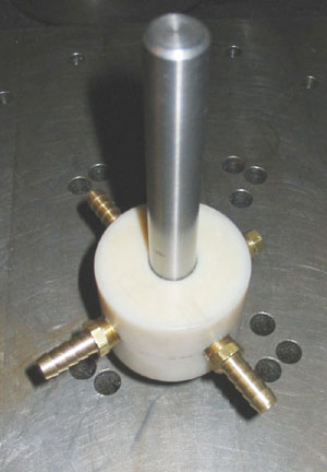
Example of a simple rotary synchronization intake cut off valve,
using 3/16 of an inch perpendicular cross holes on a 3/4 inch diam. shaft.
Valve open 65 to 75% of the time (not variable).
Alternatively, a cam on the central shaft could drive mechanical valves
located at both intake ports, with the further advantage of reducing the residual
volume between the valve and the chamber (which reduces the geometric
compression ratio). Mechanical valve driving train do not offers much
flexibility, but it is very worthwhile considering its relative
simplicity.
A variation of this simple mechanical cut off valve could be efficiently
located at each intake port, providing a proper driver gear and strap to
rotate them in phase (fixed opening duration), or better, to be driven by 2 digital electrical
motor controlled by computer (variable opening duration), and synchronized from the signal of a
microphone listening at the exhaust noise...
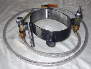
Cut off valve located at each intake port.
On the left, the shopper shaft has been removed and is shown for detail.
This accessory system is not currently offered.
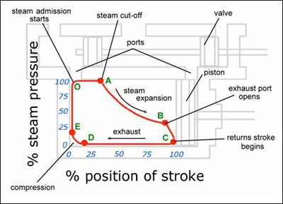
Exhaust Pressure Pulse
An other simple mechanical way would be to make use the exhaust pressure
pulse to mechanically activate the opening of an intake valve.
THEORY
« Mechanical Power Output » versus
« Intake
Cut-off Conversion Efficiently » (About « multi-stage
expander » – See comment below).
« Cut-off expansion ratio » is
about the residual exhaust pressure, which could be made zero while the
average pressure value could be substantial. If for some reason (like fine
rpm control...), the engine power need to be reduced, it could be « done
inefficiently » by reducing the motor intake pressure by a flow
restriction valve (or dissipative pin hole regulator); or it can be « done
efficiently » by cutting-off the high pressure gas sometime after intake
opening, and letting the gas to expand somewhat within the motor itself,
for a lower average effective pressure, torque and power output.
Typical volumetric expansion cycle.
«
Single Stage Expander SSE Model » (A piston in an infinitely long
cylinder) is a very convenient theoretical reference to compare expanders
between themselves. To pressured load a piston in an infinite long
cylinder, not only new gas pressure must be supplied (intrinsic energy,
later lost at the exhaust), but once this working pressure is reached,
this pressured gas column (then considered as incompressible in
transmitting forces) needs to be pushed forward (pressure flow energy)
into the cylinder in order for the piston to move and do work. « Single
Stage Expander SSE Model » piston does not recover all the incoming
pressure energy (without cut-off), because residual gas column built up in
front of the piston, and is ultimately wasted in the device exhaust.
Intake cut-off allows a pause for the gas to expand and give its intrinsic
energy to the piston. « SSE mechanical conversion efficiency » is good at
very low pressure, but fall under 42 % over 7 bar (100 psi).
QUASITURBINE PNEUMATIC / GAS
« Mechanical Power Output »
versus « Pressure Conversion Efficiently(*) »
(From Single Stage
Expander SSE Model under Iso-thermal approximation)
(Calculated values - Real world can be slightly different...)
Pressure
Cut-off (chamber %)
Exhaust
Power
Conversion
(And relative
(And Average
residual Output
Efficiency(*)
output power)
feed line flow)
Pressure
1 bar
No Cut-Off
1 bar 100 %
71 %
1 bar
50 %
0 bar
80 %
100 %
3 bar
No Cut-Off
3 bar
100 %
54 %
3 bar
25 %
0 bar
47 %
100 %
7 bar
No Cut-Off
7 bar
100 %
42 %
7 bar
12 %
0 bar
30 %
100 %
(*) « Pressure Conversion Efficiency » refer to the « Single Stage
Expander (SSE) » model (A piston in an infinitely long cylinder), and
should not be confused with the no cut-off « Comparative Efficiency to
(SSE) Model ». However, expander with known « Comparative Efficiency to
(SSE) Model» could use this table to estimate their absolute efficiency.
How to read this table:
* From the efficiency point of view: 3 bar (44 psi)
operation without cut-off gives 54 % conversion efficiency at 100 % power
output, while the efficiency could go up to 100 % if accepting to lower
the power output to 47 % (with cut off at 25 % of the chamber volume).
Then, adding 3 additional similar expanders to handle the 75 % un-used
feed line flow could allow to reach a total power of 200 %.
* From the
power output point of view: To keep the output power at 100 %, in order to
improve the efficiency toward 100 %, one need to raise substantially the
feed line pressure (Then flowing only while intake cut-off valve is open).
Such a raise in pressure may displace the motor efficiency on the
in-efficient pressure production side, with no global gain?
With intake cut-off, power and efficiency are
competing one another, such as no one can get both optimized
simultaneously. Higher is the pressure, more potential there is for
additional energy recovery by using an intake cut-off. The specific power
density of the expander decreases, as the average acting internal pressure
decreases under cut-off. Cutting-off more than necessary is simply
introducing a dead time in the power output and the intake flow. Notice
that « optimum intake cut-off » is a function of the pressure, and the
Quasiturbine allows full control on the % of internal expansion,
in
contrast with vane motors, that have fixed % cut-off incorporated into an
expander design (not variable). Nevertheless, the fixed expansion ration
is a minor defect of the vane motor, compared to their large chamber
loading losses.
Multi-stages expander
« Multi-stage expander » and « Intake cut-off » are two very different techniques with different impact
on power and specific power. Intake cut-off permit higher efficiency with
a single expander, but reduced the specific output power (consequence of
the intermittent intake flow). Another way to increase power efficiency
while keeping the full intake flow (not only for high pressure drop), is
to cascade several expanders on a common power shaft, to force near equal
stage torque (and power) contribution
(individual expander displacement
size going up as pressure goes down). Then, no intake cut-off is used, and
the residual exhaust pressure of the last stage dictate the overall
efficiency. This « Multi-stage expander » techniques is very feasible with
Quasiturbines and optimizes both the efficiency and the power output, but
it requires several expanders and is technically more complex and costly.
More Technical
quasiturbine.promci.qc.ca/QTperformance.html
Quasiturbine Rotary Expander
|
